Deep Dynamic CompactionThis method is one of the most economical and rapid methods for compacting ground to tolerate safely the weight of constructions and reservoir tanks and so on. This method effectively increases soil bearing capacity and reduces the settlement without any extra inclusion and also is ideal for mega scale projects.
Introduction
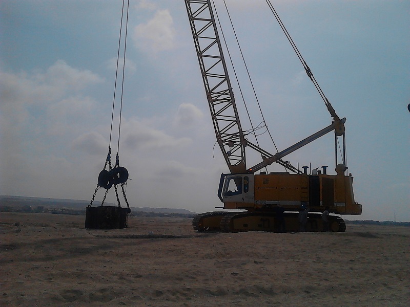
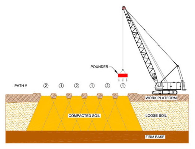
Basic Concept Deep dynamic compaction is to repeatedly drop a weight (“tamper”) freely from a height onto the ground surface in a pattern to compact problematic geomaterial to a deep depth as shown in Figure 1. Repeated impacts reduce voids, densify the geomaterial, and induce ground movement. A tamper typically has a weight of 5–40 tons and drops from a height of 10–40 m. Different from shallow compaction, deep dynamic compaction can compact problematic geomaterial down to a depth of 10 m.
The concept of dynamic compaction can be traced back to Roman times. The modern technology has been credited to the French engineer, Louis Menard since 1960s. The article published by Menard and Broise in 1975 provided theoretical bases for dynamic consolidation of fine-grained soils by heavy tamping.

Suitability Deep dynamic compaction is suitable for the following conditions:
• Loose and partially saturated fills
• Saturated free-drained soils
• Silts with plasticity index less than 8
• Clayey soil with a low degree of saturation (moisture content lower than plastic limit)
Deep dynamic compaction is generally not recommended for clayey soil with high plasticity index (greater than 8) and high degree of saturation. However, this method has been used to improve clayey soils in some countries (Han, 1998; Liang and Xu, 2011). Drainage and/or dewatering are often required to reduce excess pore water pressure in clayey soil generated by deep dynamic compaction. A certain waiting period is necessary for the dissipation of excess pore water pressure. High groundwater table (within 2 m of the starting level) minimizes the effectiveness of dynamic compaction. Under such a condition, dewatering may be necessary. Deep dynamic compaction is more economic when the area of a site is larger than 5000 m2. Due to the size of a crane for deep dynamic compaction operation, certain clearance is necessary. Table 3.8 lists adverse situations for dynamic compaction.
Applications Deep dynamic compaction has been used to improve problematic geomaterials by increasing bearing capacity, reducing settlement, minimizing collapsible potential, and mitigating liquefaction for commercial and residential buildings, storage tanks, highways and railways, airports, and harbors.
Advantages and Limitations Deep dynamic compaction can improve a large area of geomaterials in a relatively short time at low cost. It is very effective to densify loose and partially saturated fill with less than 15% fines. This method often can detect weak or loose areas during operation so
that they can be treated properly, such as overexcavation and replacement. Dynamic compaction can change a heterogeneous geomaterial to a more uniform, denser, and stronger material. The major equipment needed for this method is a crane and a tamper, which are readily available from many
contractors.
Deep dynamic compaction is generally less to not effective to improve saturated clayey soils. Special measures have to be taken for this method to be reasonably effective for these soils, such as providing drainage and/or dewatering and having a long waiting period for dissipation of excess pore water pressure. Impact by deep dynamic compaction induces noise, vibration, and lateral movement, which may cause problems to nearby buildings, substructures, and utility lines. Thismethod often requires instrumentations to monitor vibration, noise level, and ground movement.When it is used in saturated clayey soils, piezometers are needed to monitor generation and dissipation of excess pore water pressure. The tamping work may cause flying debris, which poses danger to workers onsite. The mobilization cost may be high when large crane and tamper are used.
Principles
Dynamic Densification When dynamic compaction is used on unsaturated granular geomaterial, the impact by a heavy tamper immediately displaces particles to a denser state, compresses or expels air out of voids, and reduces the volume of voids. Under such a condition, typically there is ground depression without any ground heave. A hard plug is formed under the tamper (Moseley and Kirsch, 2004).
Dynamic Consolidation The theory of dynamic consolidation was proposed by Menard and Broise (1975) to explain why saturated fine-grained soil can also be improved by repeatedly dropping a heave tamper. They attributed dynamic consolidation to four main mechanisms: (1) compressibility of saturated soil, (2) liquefaction, (3) change of permeability, and (4) thixotropic recovery. Repeated impacts do not necessarily always liquefy fine-grained soils, instead, they generate excess pore water pressure, which can accumulate under repeated loading. The accumulated excess pore water pressure starts to dissipate once tamping stops. Therefore, it is more appropriate to refer this mechanism to the generation and dissipation of excess pore water pressure.
Compressibility of Saturated Soil It is common knowledge that saturated fine-grained soil is incompressible and cannot have volume change under immediate loading (i.e., an undrained condition). Menard and Broise (1975) attributed the immediate volume change of saturated fine-grained soil to the existence of microbubbles in most quaternary soils ranging from 1 to 4%.
Generation and Dissipation of Excess Pore Water Pressure As mentioned above, dynamic compaction induces excess pore water pressure during the operation. A waiting period is necessary to dissipate the excess pore water pressure. The dissipation of excess pore water pressure is a consolidation process, which can induce settlement and compress the soil. Due to the low permeability of
fine-grained soils, prefabricated vertical drains are often installed to accelerate the dissipation. Alternatively, vacuum dewatering can be applied through preinstalled vertical vacuum pipes and horizontal drainage pipes to lower groundwater table and reduce excess pore water pressure
(Liang and Xu, 2011). Liang and Xu (2011) indicated that this method is suitable for fine-grained soil with permeability greater than 5 × 10⁻⁹ m/s.
Change of Permeability Under high-energy tamping, vertical fissures are generated around the impact points. These vertical fissures significantly increase the permeability of the fine-grained soil, which also accelerates the dissipation of excess pore water pressure and consolidation.
Figure 2 Variations of volume, excess porewater pressure, andsoil strength during and after the tamping process (afterMenerd andBroise, 1975).

Thixotropic Recovery Due to the disturbance of finegrained soil caused by tamping, it degrades and reduces its strength. This strength regains with time due to the thixotropic recovery. This is also the reason why fine-grained soils should be evaluated at least 30 days after tamping. The changes of volume, excess pore water pressure, and soil strength during and after tamping are illustrated in Figure 2.
Construction
Before construction, the equipment used for lifting and dropping a tamper should be selected based on the weight of the tamper. FHWA (1986) provided a guideline for the selection of equipment for different tamper weights as shown in Table 1. A conventional crawler crane with a single cable and a free spool is typically sufficient for a tamper weighing up to 220 kN. For heavier tampers, the crawler crane should be reinforced with stronger components. A typical flow of tamping work is shown in Figure 3 and its detailed steps are as follows:
| Tamper Weight (kN) |
Crawler Crane Capacity (kN) |
Cable Size (mm) |
| 50–70 | 360–440 | 19–22 |
| 70–130 | 440–890 | 22–25 |
| 130–160 | 890–1100 | 25–29 |
| 160–220 | 1300–1600 | 32–38 |
Figure 3 Flow of tamping work: (a) initial elevation, (b) tamping, (c) crater depth,(d) leveling and backfilling, and (e) elevation after leveling.

1. Prepare a site by removing large objects (e.g., trees), leveling the ground, dewatering, and filling existing ponds and local depressed area. If the groundwater is within 2 m from the ground surface, it should be lowered by dewatering or additional fill is placed. If the surface soil is too weak to support equipment, a construction platform should be constructed first.
2. If there are nearby existing structures or utility lines, an isolation trench is required to minimize vibration and lateral movement. Trench should be at least 2–3 m deep and 1 m wide at the bottom of the trench.
3. Place stakes at the locations for the centers of all the drop points for each pass and survey the ground elevations.
4. Position the equipment and move the tamper right above the drop point.
5. Survey the top elevation of the tamper on the ground.
6. Lift the tamper to the desired height and then let it drop freely onto the ground. Survey the top elevation while the tamper is still in the crater. Alternatively, measure the dimensions of the crater after removing the tamper. If the tamper is tilted after reaching the ground, level the base of the crater after removing the tamper.
7. Repeat step 6 until the number of drops on one tamping point reaches the target value and other criteria are met. Move to the next tamping point.
8. Repeat steps 4–7 until all the tamping points are complete for the first pass.
9. Use bulldozers to level the ground and measure the ground elevation. The difference between the current elevation and the previous elevation is the induced settlement.
10. After an elapsed time depending on geomaterial and groundwater conditions, repeat steps 3–8 until all the tamping points are complete for the next passes if needed.
11. Apply ironing tamping over the whole compaction area.
Quality Control and Assurance
Before any tamping work, the height of drop and locations of drop points should be verified. During field tamping operation, it is important to have monitoring and close visual observations. Adjustments may be made based on monitoring and observations. For example, if one drop location has a much deeper crater depth than other locations, this is an indication that much weaker geomaterial exists at that location.
Special measures may be necessary to improve this area, such as overexcavation and replacement. If additional tamping induces large heave around the crater, this is an indication that further densification is not effective so that the tamping should be suspended or terminated at this location. Common field monitoring includes piezometers in saturated fine-grained geomaterial, inclinometer casings for lateral movement, and accelerometers for ground vibrations. After the completion of the tamping work, field explorations should be conducted to evaluate or verify the degree and depth of improvement. Depending on geomaterial type and groundwater level, for coarse-grained geomaterial, the field evaluation should be performed at least in 1–2 weeks after the completion of tamping; for fine-grained geomaterial, the evaluation should be performed at least in 3–4 weeks after the completion of tamping. Field explorations include sampling for laboratory tests, SPT, CPT, or PMT. The depth of the test should be below the design depth of improvement. Static plate load tests may be performed in a large project site. Since PMT and plate load tests are more sensitive to the change of soil stiffness than SPT and CPT, they are good methods to be adopted for this purpose.
Geotechnical Design and Solution Ground Improvement Deep Foundation Earth Retention Grouting Technology Injection System Excavation and Stablization Seepage Control Slope Stabilisation Rapid Impact Compaction Deep Soil Mixing Micropile Shotcrete Anchor and Soil Nail Diaphragm Wall Secant Piles Wall Deep Dynamic Compaction Rock fall and avalanche Barrier Sheet pile wall